Prior to the commencement of any works, a survey will be carried out by the CONTRACTOR/SUBCONTRACTOR to ascertain the levels and existing site conditions. CONTRACTOR/SUBCONTRACTOR shall likewise confirm the location of underground utilities as per the given drawings of the authorities concerned.
Expose Underground Utilities
Any underground services shall be marked (highlighted) and precisely identified (depth, kind of pipe, dia. of pipe) specifying the exact location, depth & sizes. Before and after the HDD activities it should be checked/validated by the surveyor and the data of existing utilities on site if the value indicated on the approved drawing is correct versus the actual site condition of said existing utilities.
Bore Planning
After getting all utility data and the exact bore length, the bore path drawing will be prepared to obtain the proper inclination and target depth.
Pit Excavation
A clear space of at least 3 meters wide shall be maintained on all sides of the excavated area and shall be properly barricaded with hard plastic barriers if required. This area will be properly coordinated with other contractors on site (if any). Excavated material shall be placed at least 1.5 meters away from the excavation. Stringing must not obstruct the paths, road, track, or accessway. Installation of the traffic sign boards along the pipeline areas, if any Adequate lighting facilities will be provided on the job site at night work during operation, Safety Officer must be full-time available on the job site
Monitor the Project
The site engineer will monitor the progress of works in each stage of execution and report to the management
Site Mobilization and Set up
Arrangement of all related drilling equipment's on-site location requires a work site area of approximately 100 square meters. The drilling rig main frame will be positioned on the designated drill centreline of the crossing. The position of entry to start drilling will have been previously surveyed and approved. Positioning of the drilling rig will enable the support equipment to be in its proper location. The equipment required for the execution of construction works involved in drilling and installation of the product pipe section can be mobilized to the site by the Contractor as soon as the site preparation has been completed as described above.
The following sequence of activities has been summarized for the site preparation, drilling, and installation works involved in the present HDD pipeline crossing. Mobilize HDD Rig spread and auxiliary equipment to the work area and setup including anchor blocks for rig anchoring. Setup the bentonite mixing system to form part of the setup of the entire rig spread.
- Prepare and set out a survey system at the entry section and at the exit area.
- Calibration of steering tools.
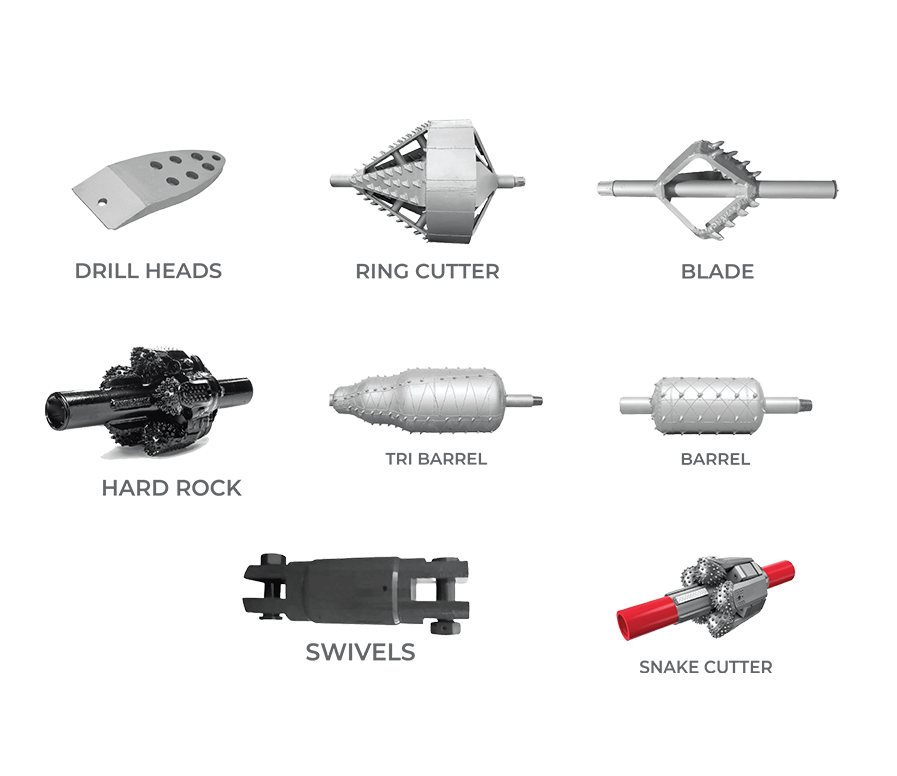
- Execute the pilot hole with a 6.1/2" downhole drill head considering hard strata and the drill bit to punch out at the designed exit point.
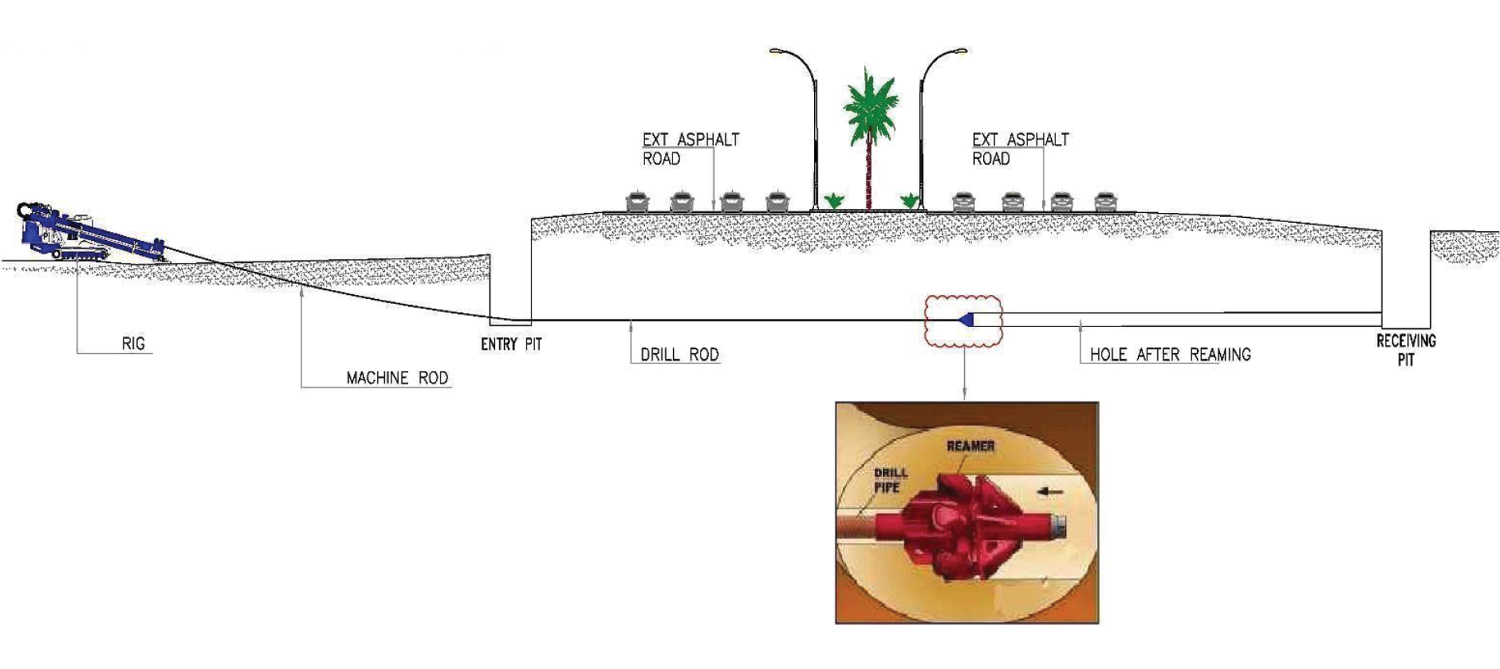
- Connect rock master reaming tool, conduct borehole reaming pass in reverse mode until reamer emerges at the entry point.
- Perform borehole cleaning and passes with a rock master reaming tool as required.
- Disconnect reaming tool and hook up the pipeline section.
- Place the pipeline section on roller supports (or on the ground with the aid of side booms or excavator), aligned with the HDD borehole.
- Connect the pre fabricated pipeline section to the HDD rig via PPA, and pull the head and the drill string.
- Install the pipeline section by pulling inside the bore- hole until the pull head reaches the pre-defined position the at HDD exit pit allowing for subsequent tie in operations to commence.

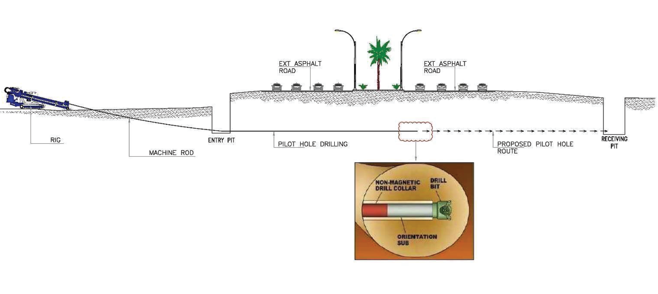
The first step in the HDD Installation is to drill a guided pilot hole that deliv- ers the drill bit and bore head to the surface at the specified entry point to the exit point. This pilot head is designed in such a way that it can be steered horizontally or vertically based on the requirement of drill path design.
To drill in the soil the rotating drilling head has to cut a micro tunnel into the soil supported by a high-pressure jet of bentonite Slurry. This equipment is called jet assembly. The drilled soil material flows back into the start pit transported by the drilling mud.
To follow the designed drill run the drilling tools are equipped with a transmitter, which gives permanent information about the drilling tool's depth, distance, inclination, and direction.
This information is reported on a drilling report to provide the as-built documents. The transmitter gives a signal to the surface above, where a receiver is picking up permanent information.
To follow the drilling tool one person has to walk and stay over the tool and hold the receiver. On road crossings, one line has to be blocked for a few minutes while the drilling Tool is moving under it. The receiver sends the information to a remote control panel on the drilling ring. The driller can correct the position of the drilling tool and can keep it on the designed curve.
Receiving the signal from Transmitter For long distance drilling like River Crossings, Highway Crossings, or to a drill under buildings where the tool cannot be located with the Radio Detection System, a Wire line Steering Tool is installed behind the Drill's head. All the information about depth, distance, inclination, and azimuth, is sent from the downhole through a wireline in the Drill.
Rod into a computer. The Steering Engineer and the driller can keep the Drilling tool on the designed curve. The size of the pilot hole is approx. 150 mm and the mudflow is approx. 35-40 Gallons per Min.

Reaming is a process to enlarge the pilot hole to a suitable diameter for the product pipeline. The Reaming operation consists of using an appropriate tool to open the pilot hole to a slightly larger diameter than the carrier pipe- line. Generally, the reamer is attached to the drill string on the bank opposite the drilling rig, rotated, and pulled back through the pilot hole. A large quantity of slurry is pumped into the hole to maintain the integrity and flush out the cuttings.

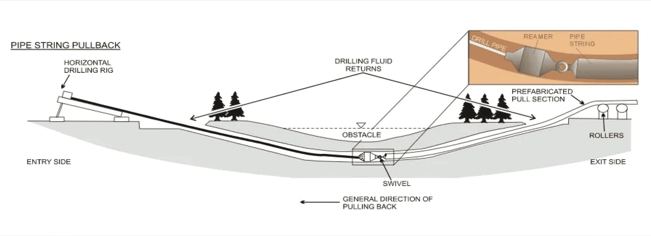
The pull-back operation involves pulling the entire pipeline length in one segment back through the drilling mud along the reamed-hole pathway. Proper pipe handling, cradling, bending minimization, surface inspection, and welding procedures need to be followed.

The pipe is connected to the reamer with a towing head and a swivel. The swivel is preventing any translation of the reamer's rotation into pipe string, allowing for the smooth pull into the drilled hole.
